-40%
High-resolution LED bargraph display
$ 10.56
- Description
- Size Guide
Description
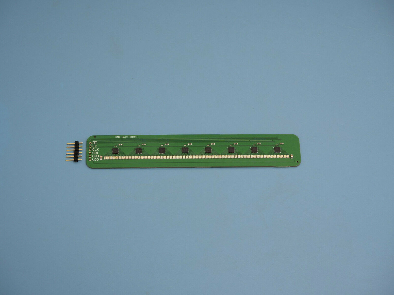
Need a high-resolution discrete linear indicator? This design is a linear array of LEDs that has a resolution of 128 points/steps at 1 mm spacing. The display is controlled through a serial peripheral interface and and can be optionally dimmed with a PWM signal. The board dimensions are 25 x 150 mm.This board combines 128 densely-placed SMD LEDs and shift registers to create a linear indicator that is easy to control from popular microcontrollers. The serial interface makes it possible to control 128 LEDs with only 6 pins.
The display can be controlled using the built-in SPI (serial peripheral interface) connection on most microcontrollers (Arduino, STM-32, ESP32, nRF5). A demo Arduino sketch is available here: https://cdn.hackaday.io/files/1735157423665760/LEDLineDemo.ino
Pin descriptions and hook-up directions:
VDD
: supply voltage, must not exceed 6 V. 5 V and 3.3 V tolerant. Current draw is 2 mA per LED when PWM dimming is used.
GND
: power ground
CLK
and
SDI
: clock and serial data lines. Connect these to the SPI pins (SCLK and MOSI, respectively) on your microcontroller. Send a string of 128 bits (16 bytes) to set the state of the LEDs. Bits are shifted from left to right (as viewed with the interface pins on the left),
i.e.
, the last bit sent will control the first LED on the left.
LE
: latch enable. Pulse this pin (turn it on, then off) after sending the serial data to make the new values effective in driving the LEDs.
OE
: active-low output enable. Pull this pin low to turn on the display. Pulling this pin high will blank the display. Connect a PWM output pin to OE to dim the display, or tie to ground to leave the display permanently on at full brightness.
A 6-pin section of .100" breadboard header is included. For board integration, a footprint for a JST PA series connector is left unpopulated on the back on the board. The part number for this header is SM06B-PASS, available from many component distributors.
